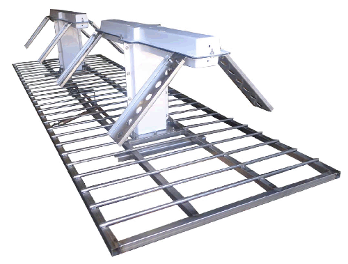
SWDDP VHF SERIES
HORIZONTALLY POLARIZED DOUBLE
DIPOLE DOUBLET ANTENNAS
SWDDP SERIES
Frequency Range: Band III (174-230 MHz)
Polarization: Horizontal
Power Rating: 3 kW Per Bay
System Input: 7/8″EIA or 7/16″ DIN
Half Power Beam Width: 3 dB / 90°, 6 dB / 120°
Circularity: ± 2 dB (3 ft. face)
VSWR: 1.08:1 Across the Band
Single Panel Gain: 11dB

Features:
•DESIGNED FOR HIGH BAND VHF BAND III
Channels 7 to 13+ (174 – 230 MHz).
•SUPERIOR BANDWIDTH ACROSS THE ENTIRE BAND
Typical single channel on carrier < 1.05:1 or better. Entire band
< 1.1:1 VSWR.
•OMNI DIRECTIONAL OR DIRECTIONAL PATTERNS
Many standard patterns available. SWR, Inc. can also provide patterns for specific coverage areas and FCC filing documentation.
•BEAM TILT AND/OR NULL FILL AVAILABLE UPON REQUEST
•RUGGED CONSTRUCTION.
Each panel is constructed of high grade 304 stainless steel which provides excellent corrosion resistance and optimal mechanical properties. The balun assembly and feed system are built with high quality copper and naval brass.
•PRESSURIZED AND GROUNDED
The antenna system is pressurized to the feed point of each bay and each bay is DC grounded.
•WEATHERIZATION (OPTIONAL)
Radomes or electrical deicers available for areas that experience periods of heavy icing and/or snow conditions.
•CUSTOM MOUNTING BRACKETS AVAILABLE
•SINGLE PANEL MODELS AVAILABLE
•WARRANTY
2-year limited warranty on defects and workmanship to the original purchaser.
Notes:
1. Weight and windload do not include mounting brackets.
2. Windload based on 50/33 PSF. Channel 13, per EIA standard RS-222-C.
3. SWR, Inc. maintains a continuous program of product improvement and therefore reserves the right to change specifications without notice.
SWDDP VHF
Electrical and Mechanical Specifications
| # of Bays | # of Panels | Power Gain | dB Gain | Weight in Lbs. | Windload in Lbs. | Antenna Aperture |
|---|---|---|---|---|---|---|
| 1 | 2 | 6.63 | 8.21 | 258 | 540 | 9.7 ft. |
| 3 | 4.51 | 6.52 | 387 | 748 | ||
| 4 | 3.32 | 5.23 | 516 | 920 | ||
| 2 | 2 | 13.21 | 11.21 | 516 | 1073 | 20.3 ft. |
| 3 | 8.94 | 9.51 | 774 | 1463 | ||
| 4 | 6.61 | 8.24 | 1032 | 1828 | ||
| 4 | 2 | 26.32 | 14.22 | 1032 | 2132 | 41.9 ft. |
| 3 | 17.84 | 12.53 | 1548 | 2920 | ||
| 4 | 13.22 | 11.22 | 2064 | 3644 | ||
| 6 | 2 | 39.81 | 16.04 | 1548 | 3190 | 62.5 ft. |
| 3 | 26.94 | 14.31 | 2322 | 4372 | ||
| 4 | 20.03 | 13.01 | 3096 | 5463 | ||
| 8 | 2 | 55.01 | 17.43 | 2064 | 4249 | 85.1 ft. |
| 3 | 35.52 | 15.52 | 3096 | 5825 | ||
| 4 | 26.33 | 14.21 | 4128 | 7280 |
